
Credit: Fabhead
When you print something on your 3D printer, the design doesn’t just go from the CAD software to becoming a physical object. The design needs to go through slicing first.
Slicing is a critical step in the process that defines how your 3D objects should be printed. Learn more about slicing and the crucial slicer settings below.What is a slicer?
Your 3D printer, be it technologically advanced as it is, cannot read your 3D CAD model on its own. It needs to be converted into a set of instructions on how it should be printed.
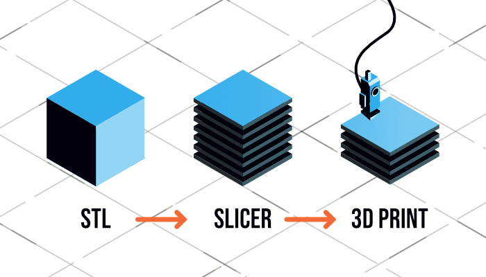
Here is where the slicer program steps in. The slicer “slices” your CAD model into layers with explicit instructions on how much material should be used, how long and fast it should be printed, and where the material should go.
When you design a 3D model on CAD software, it generates an STL file. This STL file is then converted by a slicer to become a 2D model or G-code.
In the slicer program, you can control the following settings:
- Printer settings: print bed shape, Z offset, and nozzle diameter
- Filament settings: extrusion multiplier, print bed, extruder temperature, and filament diameter
- Print settings: shells, infill per cent, speed, and layer heights
Here are the 7 key slicer settings that every 3D printer beginner should know
1. Shell thickness
The shell of a model is the outer wall. With the shell thickness setting, you can adjust the number of layers that the shell will have. Higher shell thickness means more layers and thickness to the wall.
By creating thick walls, you make the object more durable. However, intricately designed and decorative models will do better with thinner shells as it might distort the design. It could also produce no visible effects on the model so it would be a complete waste of filaments.
Be careful not to set it too thin as the infill might peek through.

2. Infill density
Infill (or fill) density is the material that will be printed inside your model. It is typically measured in percentage of the thickness.

Photo from TianseOffice.com
As you can see, it goes from 0% (virtually hollow inside the shells) to 100% (full). The higher the infill density, the longer your print time will take. Consequently, this also means that your object gets stronger and heavier the more infill it has.
For more infill info, check out our blogs on infill.
Choosing the Right Infill for your 3D Print
3. Top/BottomThickness
After the infill, you need to determine how thick the top and bottom are going to be before starting the infill. This is different from the shell as it refers to the walls on the outer sides of your model.
The top thickness of the object prevents pillowing and sagging. On the other hand, the bottom thickness influences the strength and stability of the base of your object.
This setting works hand in hand with layer height, especially if you choose a thin layer height level. If the bottom or top layer is too thin, the infill might peek through. To prevent this, the top and bottom layer should be 6 to 8 times greater than the layer height.
4. Layer height
The layer height is the height of each layer in your 3D print. It affects the resolution of the model with thicker heights producing fewer details, rougher surface, and more visible layer lines while thinner heights create finer details and blend layers into one another.
Thinner layer heights also take longer to print as it would mean that there will be more layers to print.
Layer height is also crucial to a successful first layer. A higher value in layer height will reduce the effects of slight errors in levelling.
However, be careful not to set it too high when using a small nozzle as it may cause layer separation and splitting. It is a rule of thumb that the layer height you choose is 20% smaller than your nozzle diameter to allow for layers to bond together.
5. Print Speed
Print speed refers to the movement speed of the print head while extruding filament. The faster the speed, the faster the printing time. However, choosing the wrong setting can cause so many issues so beware.
Complex and detailed objects require a slower print speed to capture the details. Some filaments also benefit from slower print speed as it improves their bed adhesion and extrusion flow.
Simpler objects using PLA will fare well even with the fast print speed.
For more tips on bed adhesion, check out our guide.
6. Retraction
Retraction is a setting that slightly sucks the filament back in as the print head travels from one print point to another. Simply put, it prevents the filament from dripping out in places where it’s not supposed to, leaving strings in between point a to point b.
This is particularly useful for designs that have gaps in between (such as bridges). The slicer program should detect this in your CAD file and automatically turn on the setting.

What lack of retraction looks like
7. Spiralize outer contour (Z-scar)
In most prints, there’s a single point where each layer begins and ends. This makes an unsightly “zipper”-like mark on the objects called the Z-scar. It not only doesn’t look good but it also affects the structural integrity of the object.
To prevent this, you should activate the Spiralize feature on your slicer. It allows your 3D printer to print in one continuous line from the bottom to the top, removing a single start and stop point.
Note on slicer settings
It is not important to activate all of the above settings in a single project. Only adjust the setting when it’s important to your design (e.g., slower print speed and lower layer height on fine details). It also helps to try it one at a time and note down the effect that it has on your object.
If you encounter any 3D printing issues, please check out our Comprehensive Troubleshooting Guide. Alternatively, you can contact us for inquiries by email or phone.